Diagram of a Small Loop Antenna
I have been experimenting with small (generally less then 1/10 wavelength circumference) transmitting loop antennas in the HF bands since the 1980's. I had made several discoveries for myself but eventually I saw these antennas in the Communications addition of a military equipment publication called the Jane's Catalog. I had no other source of information so I reverse engineered these antennas from photos alone. Later I learned that these were pretty well known antennas [ref.]. The ARRL Antenna Handbook's equations helped me put a little design effort into these antennas so that I could make them work the way I wanted them to work. These days the Internet is a gold mine of small loop antenna information.
I find small transmitting loop antennas very useful when space for a full size antenna is limited. When care is taken during the construction to minimize resistive losses, performance can be very respectable. Users of this antenna, including the military, have reported very good results even when mounted close to the ground. I have used small transmitting loop antennas close to the ground, leaning up against wooden fences, and indoors with very acceptable results. Beware however that the fields near this antenna are very strong so don't plan on using any more then QRP power levels unless you can get the antenna up and away from people. This type of antenna is ground independent in regards to not needing a separate return to function. However, like all antennas the further you get it from the ground or the better the quality of the ground the lower the ground losses will be. In general, a small transmitting loop antenna will perform well even close to the ground when mounted vertically and will exhibit useful sharp nulls in the azimuth pattern. When orientated horizontally the azimuth pattern will be omni-directional but will have an elevation pattern similar to a horizontal dipole at the same height with the exception of a constant null at the zenith.
If you are skeptical about the performance of small loop antennas, just remember that no black magic is being suggested here. These antennas still have to adhere to the laws of physics, just like any other small antenna. Remember the following:
You can have any TWO of the following antenna parameters:
You cannot have all three. In other words, small transmitting loop antennas sacrifice bandwidth for small size and efficiency. The more efficient they are, the more narrow the frequency range in which they can operate. If you have built a wide bandwidth, small antenna then you cannot have good efficiency. You have probably built a dummy load! If you do seem to have all three then your feedline is part of your antenna system and you don't really have a small antenna.
I have built small transmitting loop antennas for frequencies ranging from 3.5 to 450 MHz. The practical upper frequency limit for a true and efficient small loop appears to be about 60 MHz. The loops I have built for higher frequencies exhibit the useful sharp nulls and very narrow bandwidth but even for very thick conductors the loss due to the skin effect is just too high for transmitting applications. The UHF loop described later this page is very small and was made as efficient as possible without resorting to silver plating or superconducting construction yet it still gets very hot with only 10 watts of RF at 445 MHz. Loops at the upper frequencies may still be useful for receive only applications such as radio direction finding or use as a front-end bandpass filter.
Diagram of a Small Loop Antenna
Equivalent Circuit [3]
Magnetic Loop Antenna Pattern
A small loop antenna appears as a very large resonant circuit. The loop itself can be viewed as a large single turn inductor of this circuit. Due to the large (relatively speaking) size of this inductor, radiation very easily takes place. Experimenters have noticed that the more turns there are to this inductor, the less efficient it is. For some low frequency loop antennas several turns may be required to obtain resonance but radiation efficiency usually suffers. Basically, the radiation resistance increases as the loop size increases. The higher the radiation resistance, the higher the efficiency assuming a constant loss resistance. Increasing the number of turns in a loop increases the inductance but also increased the loss resistance. Taken to the extreme, ordinary tank circuits don't radiate much at all due to the small, multiturn inductors.
Because of the very low impedance of a small transmitting loop antenna, coupling energy to it from 50 ohm coax can be rather confusing. I have found this to be easily accomplished by transformer coupling (see the above sketch) via a small coupling loop or by autotransformer coupling (similar to a gamma match) by means of a tap up the conductor (as described later). Some earlier designs (i.e., Army Loop, Patterson Loop) used a rather complicated capacitor feed system that I have never had any desire to duplicate. With a small coupling loop it is very easy to just slightly oversize the coupling loop and then rotate the coupling loop relative to the main loop to obtain a perfect match. With loops made from small conductors I've had good success using transformer coupling with a small toroid.
There are a lot of misconceptions about small loop antennas. Small loop antennas are often referred to as magnetic antennas. This is because they mostly respond to the magnetic component of an electromagnetic wave and transmit a large magnetic component in the extreme near field (<1/10 wavelength distance). In the far field (>1 wavelength distance) the RF from a small loop is the same as that from any other antenna being composed of both electric and magnetic fields. In fact, at distances between about 1/10 and 1 wavelength it responds more to the electric field then the magnetic! It is often believed that magnetic antennas will not respond to local noise because local noise is mostly composed of electric fields. This is ONLY true if the offending source is in the extreme near field (reactive field) of the loop antenna AND if the source is truly of electric field origin. An example of this might be a high impedance power transmission line that had an arcing insulator and was right next to the antenna. In this case a small loop may not respond to the interference as much as say a dipole would. The same can not be said if the offending transmission line was miles away. This is because you cannot have a time varying electric field without generating a time varying magnetic field and vise versa. This is basically what generates an electromagnetic wave anyway. It is worthy to note though that due to the two sharp nulls in the small loop's radiation pattern it is very easy to null out local interference while still obtaining large azimuth coverage area. Also, unless the loop contains a well balanced capacitive (electric field) shield it may still respond to very close electric fields due to capacitive coupling. In my experience small loop antennas usually have higher signal-to-noise ratios then larger antennas.
The polarization of this antenna is mostly aligned with the physical orientation of the loop and is due to the high current within the loop conductor. A smaller amount of cross polarization occurs in the null direction looking into the plane of the loop due to the high concentration of E field across the capacitor. In free space both polarizations are present although the polarization aligned with the loop dominates. When mounted close to the earth and orientated vertically the horizontal component mostly cancels out and leaves only vertical polarization as a useful component. When orientated horizontally the main polarization component is horizontal and for effective operation the antenna should be mounted at least 1/2 wavelength high to have an effective radiation pattern. A horizontal loop should be treated the same as a horizontal dipole in regards to height. A vertical loop works very well at low heights. This all assumes of course that the dimensions of the antenna are small enough to be considered a true small loop. As the loop is made larger it begins to diverge from being a "magnetic dipole" and the pattern and polarization can change. Taken to the extreme a full wavelength loop has a pattern very different to that of a small loop.
Reference Diagram of a Small Loop Antenna
Total Pattern (V & H Pol Combined)
Blue - Viewed along Y-axis
Red - Viewed along Z-axis
Pattern Viewed along Z-axis
Black - V-Pol
Red - H-Pol
It is my opinion that small loop antennas perform so well at very low heights (when mounted vertically) because in the extreme near field (less than 1/10 wavelength) most of the loop's field component is magnetic and magnetic losses in ordinary ground may be less then the dielectric losses that most antennas (i.e., dipoles) with a large electric field component are subject to. For example, if either or both ends of a dipole are close to the ground a significant amount of "displacement current" will travel to the ground inducing return currents back through the earth which would otherwise contribute to radiation. In effect the ground becomes a series resistance between the ends of the antenna. With a small loop these displacements currents are very concentrated in the space between the capacitor plates and the ground plays little part unless the capacitor itself is near the ground. However, at a larger distance from the antenna the far field energy will still be affected by the lossy ground [3] like any other antenna but there usually isn't much that we can do about that ground short of placing the antenna on a seaside beach.
There have been claims that a vertical small loop does not suffer from the pseudo-Brewster angle notch-out effect that other vertical antennas will have when installed over real ground. I have not uncovered any theory to back this up and my first thought would be that a vertical small loop should act like any other vertical antenna in this regard. However, the real world experience of users would indicate that this phenomenon may need further investigation.
There is a general lack of measured data comparing small transmitting loop antennas to some sort of standard antenna. I have only found a small bit of recent data [2] comparing an 1.7m AMA 8 Loop to a 20ft marine whip and against predicted data for an optimized 20ft center loaded whip. The whip was tuned with an autotuner and a copper plate was submersed in seawater for a ground. The data was collected from 2 to 14 MHz. The loop consistantly outperformed the 20ft autotuned whip by about 3 to 4 dB. The loop overtook the predicted achievable gain of the optimized whip at all frequencies above 8 MHz. The data was collected via groundwave. The same author extrapolated the NVIS (zenith) gain of a Racal Mini-Loop Model MLA (1.53m x 2.1m) by comparing the antenna to resonant dipoles of known gain with a receiving station that was at a 100 km distance. The best that I can read from the small graph showing his data the NVIS gain was about -8.7 dBi at 2.6 MHz and rose up to 1.8 dBi at 5.9 MHz.
The main difference between mounting a small loop vertically or horizontally is the polarization and the orientation of the antenna's pattern null. E-field losses would conceivably be greater for a horizontal loop that is close to the ground. Some literature I've read suggest that the pattern for a horizontally mounted small loop will have a lower take off angle then other horizontal antennas. I've seen no justification for this claim except that there will always be a null straight up (broadside) due to the nature of a small loop antenna's free space pattern and this will cause there appearance of a lower angle of radiation compared to a low dipole that has the main lobe straight up. This can be viewed like a low dipole elevation pattern (a wide lobe straight up) with a notch taken out at the zenith (90 degrees). However, when the far fields are compared at a lower angle, such as 10 degrees, the results are more comparable. I will soon have some pattern comparisons below to show this.
Since most of the near field component is magnetic the antenna should be placed at least 1/10 wavelength away from ferrous objects, such as steel towers, iron framework, etc. These objects may create loss due to eddy currents that get setup within them. Ordinary copper house wire may or may not be a loss factor depending on resonances in the wiring, wiring loop areas, etc. In some cases coupling to external wiring may actually increase the performance of a small loop antenna although I do not have measured data to prove this. However, contrary to my results with other indoor antennas I have had very good luck using small loops indoors.
Radiation Resistance, Ohms: RR = (3.38×10⁻⁸)(f²A)2
Loss Resistance, Ohms: RL = (9.96×10⁻⁴)(√f)(S/d)
Efficiency: η = RR/(RR+RL)
Inductance, Henrys: L = (1.9×10⁻⁸)S[7.353log10(96S/πd)-6.386]
Inductive Reactance, Ohms: XL = 2πf(L×106)
Tuning Capacitor, Farads: CT = 1/2πf(XL×106) includes distributed capacitance
Quality Factor: Q = (f×106)/Δf = XL/2(RR + RL)
Bandwidth, Hertz: Δf = (f×106)/Q = [(f1-f2)×106]
Distributed Capacity: pF: CD = 8.92 * radius
Capacitor Potential, Volts: VC = √(PXLQ)
Capacitor Voltage Rating: 75,000V/in
where
f = operating frequency, MHz
A = area of loop, square feet
S = conductor length, feet
d = conductor diameter, inches
η = decimal value; dB = 10 log10η
P = transmitter power, Watts
Construction of a small loop is pretty straight forward. Simply choose the desired loop diameter based upon materials available and performance desired. The larger the loop diameter, the greater the efficiency. If it is made larger then about 1/10 wavelength in circumference it will no longer be classified a small loop and its radiation pattern will begin to change. You may not care about this. Choose a conductor with as large diameter as you can find and it preferably should be copper (or silver). This is to keep the resistive losses low. The conductor does not have to be solid. I once used some 3/8" Heliax coax for the main loop and had good results. Heliax cable uses a corrugated copper tube for the shield. A common idea is to use a thick braid to connect the capacitor to the main loop but be cautious if you do this. I once used a braided conductor to connect from the main loop to the tuning capacitor and the braid actually got hot! My experience is that losses are actually higher in braid at high RF currents then for solid wire or tubing. I think this phenomenon need further research. If something gets hot in an antenna then there is no doubt that losses are occurring at that point.
Choose a capacitor value that will resonate the loop to the desired frequencies of operation. The capacitor is the most difficult part of constructing this type of antenna. Because of the very high Q, most available capacitors will start arcing over at powers as low as 10 watts. Remember that even with only a few watts of power, there can be thousands of volts across the capacitor and several amps of current through the capacitor (not necessarily in phase, no free power!). Losses in conventional capacitors can be high due to the several milliohms of resistance found in their brush contacts and non-welded vanes. For this reason you should try to find or build a split stator capacitor of some sort with welded vanes. The idea is to not have RF current flowing through any moving and/or mechanical contacts. The spacing of the plates will have to be large unless low power is used. If you are using QRP power levels and all you can find is a single stator/rotor capacitor go ahead and use it. Just be aware that the losses will most likely be greater in this type of capacitor. I have made small loop antennas using conventional broadcast receiver capacitors and they worked well for QRP use although I know their performance could have been better. Some folks have built "trombone" style capacitors out of copper tubing for low loss/high power performance. Some form of reduction drive is highly recommended for any tuning capacitor due to the very sharp tuning of the high-Q antenna. Also, if used outdoors for long periods of time you will want to protect the capacitor from water and insects.
To couple energy into the loop several methods are available. By far, the easiest method is to simply construct a coupling loop as indicated in the sketch. No physical connection is required between this coupling loop and the main loop although no harm will come if you want to connect the bottom shield of a sheilded coupling loop to the bottom of the main loop. For capacitive shielding properties, you may want to construct a shield coupling loop. This will supposedly ensure that only magnetic coupling occurs between the primary and secondary loops. I have not performed any comparisons between shielded and un-shielded coupling loops but they both work without any problems. RF probe measurements have indicated no common mode currents on the feed line in both cases and the antenna patterns are well defined in both cases so balance does not seem to be problem. To create a shielded coupling loop simply take the end of the feed line coax and loop it back upon itself to form the desired loop dimensions. Where the loose end meets the coax again, strip and solder both conductors of the loose end to the shield of the coax. At the top of this coax loop, cut the shield and produce a small gap all the way around the coax. The shield should be totally separated at this point. This style of shielded coupling loop will make the entire antenna system unresponsive to electric fields. If the small coupling loop is made slightly larger than is necessary then one can adjust the coupling by rotating the small loop inside the larger loop. This makes for a very precise method of adjusting the coupling. Another method of coupling to the main loop is via an autotransformer style coupling. With this method, the shield of the coax is connected to the bottom of the main loop and the center conductor of the coax is connected to the main loop several inches from the shield connection. This connection point will have to found experimentally and doesn't lend itself to easy adjustment but it will work just find electrically. This method resembles the "gamma" style match of Yagi-Uda arrays without the series capacitor. There are also capacitive methods to couple to the main loop using a capacitive voltage divider technique (Patterson Loop) that require several high quality capacitors and I have no experience with it. You're on your own here. Whatever method you choose to couple the feed line to the antenna the coupling should be adjusted for the lowest SWR at resonance somewhere near the center of the antenna's designed frequency coverage. Once the coupling is adjusted no further adjustments of the coupling will be required throughout this range. This is yet another beauty of this type of antenna.
I have read some discussions about the need for extreme balance in the antenna in order to have deep nulls and no common mode currents. My experience with all of the feed methods above has indicated that this is not as big of an issue as some may think. The feed point is at a very low impedance point of the antenna and maybe I've just been lucky, but RF current probe measurements of the outer surface of the feed line and well balanced deep nulls in the antenna patterns indicate to me that the balance must be pretty good.
I hope you find the following spreadsheet that I wrote to help me in the design of these antennas useful. Please note that where it calls for a resistance loss in milliohms that this is only if you want to estimate additional sources of loss such as that from poor connections. The programs assume a copper conductor and the resistance for a copper conductor is already accounted for. Also note that the spreadsheet will inform you of a maximum loop circumference for the loop that will give you the so called small loop performance. If the diameter of the loop is increased beyond this value the efficiency will increase but the pattern will change. The extreme example of this would be if you were to increase the size to a full wavelength. The efficiency would be very high and the pattern (broadside pattern) would be opposite that of a small loop. Many small loop antenna experimenters recommend circumference of 0.25 wavelengths as a good compromise between efficiency and useful pattern.
Note: The spreadsheet below is a work in progress from a software routine I first wrote about 1990. I am in the process of doing a major overhaul to clean up the application and incorporate all that I have learned over the years from a great many folks that have provided input to me. Therefore, aa5tb_loop_v2.00 is in the works and will include Kai Siwiak, KE4PT's "null depth" calculations [8] among other improvements.
aa5tb_loop_v1.22f.xlsx - Microsoft Excel Application with modifications by Kai Siwiak, KE4PT. Also opens in Libre Office.
I started experimenting with small loop antennas around 1988 and I had no data except for photos of military loop antennas I had seen in the Jane's catalog. My first attempts were trial and error but I had pretty good success. Below are some photos from August 8, 1991 of one of my first successful loop antennas. It tuned from 4.8 MHz to 17.5 MHz and I used it for a number of years. It was constructed from 3/4 inch copper tubing and was fed using the autotransformer type of coupling. The main tuning capacitor was a 500 pF air variable.
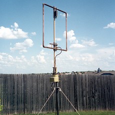
(click to enlarge)
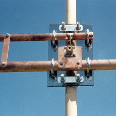
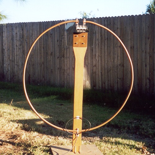
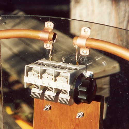
This loop is 3 feet in diameter and is constructed of 5/8" copper pipe. I used 2 sections of a three section variable capacitor. One side of the loop is connected to one stator and the other side of the loop is connected to the other stator. This is equivalent to two capacitors in series with the rotor being common to both. With this arrangement no current flows through the lossy brush contacts. A capacitive shielded coupling loop is used to feed the antenna.
(click to enlarge)
This loop has performed very well for me. It will tune from about 9 MHz to 28.5 MHz.
The main problem that I've always had with magnetic loop antennas is that they are not very easy to transport in the field. I've always wanted something that I could fold up and take with me to the field and then deploy at a campsite. Unfortunately, portability and efficiency are difficult to be had at the same time when we're dealing with small loops. Any kind of flexible joint usually has enough resistance to seriously affect the antenna's efficiency.
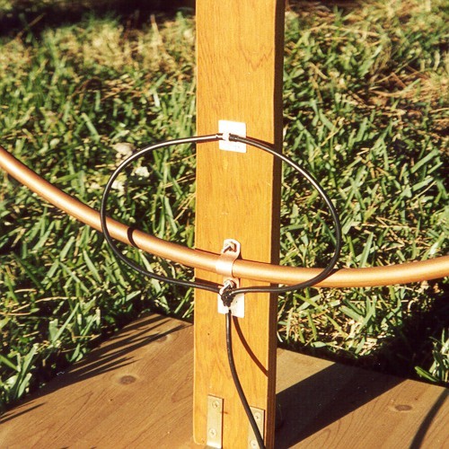
I constructed a couple of prototypes that are both tuned to 30m. The first loop is made from RG-8 coax and despite previous experiments with high power that indicated to me that braid was not a good idea for low radiation resistance antennas I chose to do so anyway for the sake of portability. The antenna is square and in the first experiment I supported the loop with rope and sticks inside my house. This was also the first time that I fed a small loop with a small ferrite coupling transformer. I used the coax itself as the capacitor. With my antenna analyzer I was quickly able to tune the loop to the middle of 30m by trimming the coax.
With my transmitter set to 5 watts output I promptly made several successful QSO's.
On the next nice day I took the antenna outside to do some further experimentation. The antenna performed very nicely although I don't have any quantitative data on it yet. When I get some more time I'll put more details on the Web so that it can be easily constructed but for now take a look at the photos below.
(click to enlarge)
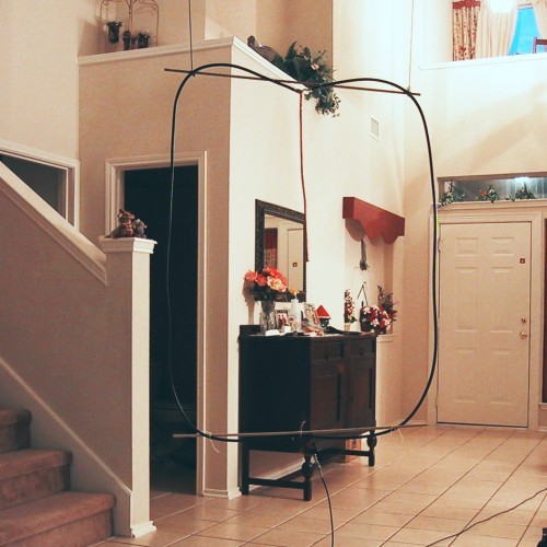
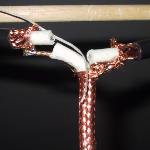
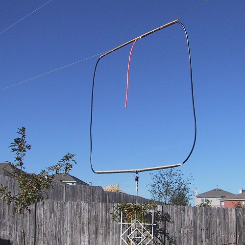
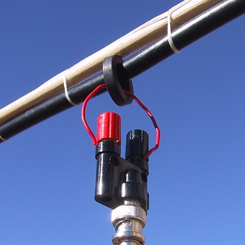
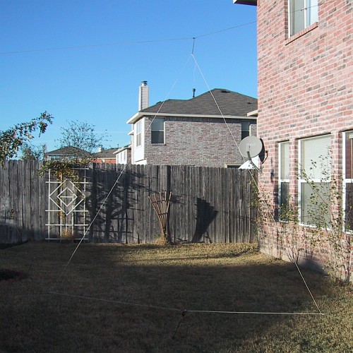
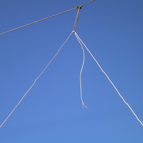
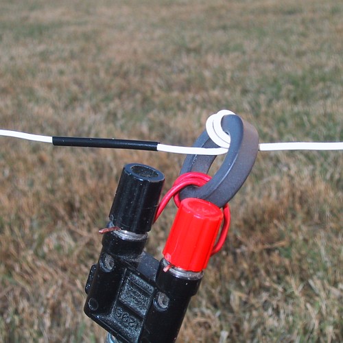
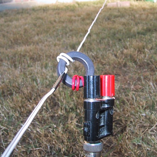
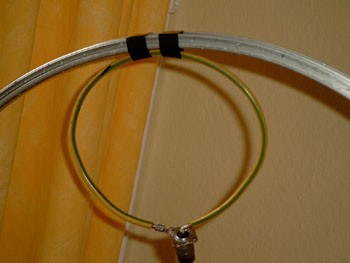
Later, I decided to develop a loop that could be hung from a single support and be folded up to carry in a small backpack or sack. Using 22 AWG solid insulated copper wire I constructed the antenna as a delta loop. Since I knew the efficiency would be low I made the loop larger then normal to make up for it. For the capacitor I constructed a "gimmick" capacitor by leaving the ends of the wire pair together and letting their proximity to each other provide the capacitance. Once again I trimmed the "capacitor" (wire pair) until I was close to the design frequency. I simply split the ends and moved them around to fine tune the antenna to the exact frequency. Initially, I just cut a length of the parallel wire to the desired circumference and then split the wire up to the "gimmick" capacitor. I then installed the ferrite toroid and soldered the ends together.
Even though I'm sure that the efficiency of this antenna was low I had a nice 30 minute QSO to New Mexico with it at 5 watts just before these photos were taken. Once again I hope to have more details available soon. Here is a hint: The larger the loop, the more turns that are needed on the primary (red wire) to obtain a 1:1 VSWR at the resonant frequency.
(click to enlarge)
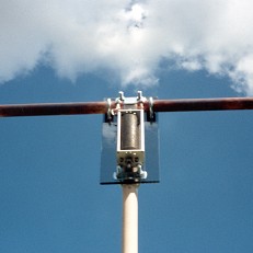
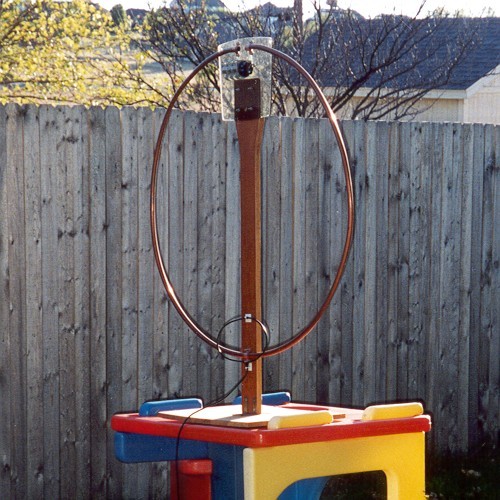
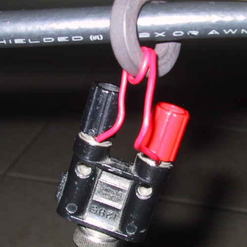
Below is a small (3" dia.) capacitively shielded loop antenna that I developed for two meters. It is constructed of semi-rigid coax (solid copper shield) and the small coupling loop can turn inside the main loop. I really only built this loop for demonstration purposes but it does work. The bandwidth is only about 100-200 kHz (at 146 MHz) but it does work at least as good if not better then a standard "rubber duck" antenna. The two sharp nulls in the plane of the loop are very pronounced and can be used for direction finding purposes.

(click to enlarge)
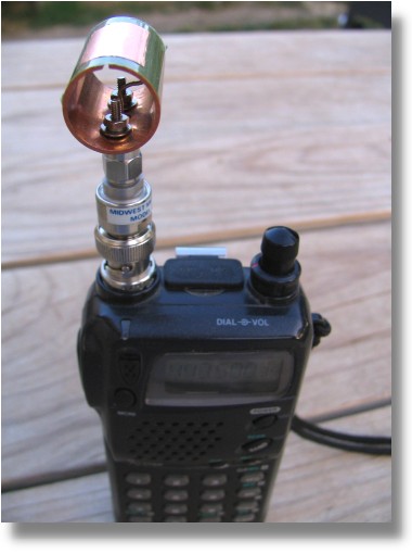
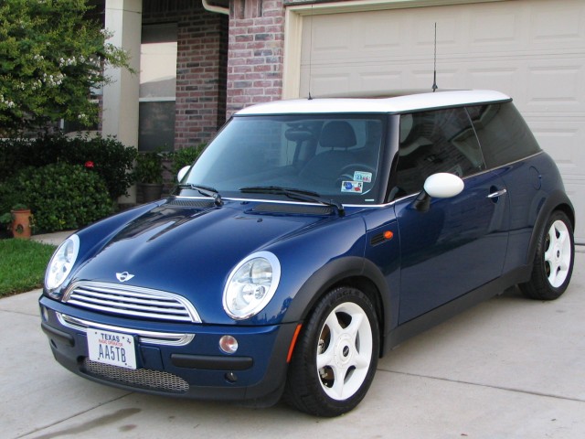
I purchased a Mini Cooper in 2004 and I was trying to come up with various ways to implement a disguise antenna. I thought about hiding a UHF antenna in the rear spoiler. Just to see if it could be done I created a small transmitting loop for the 70cm band that could easily be hidden. To make the conductor as large as possible I used a 5/8" copper water pipe coupler piece as the main loop and cut a slit in it at the top to create the top gap in the loop. An insulating tape with copper tape on top of that form the tuning capacitor. The loop's conductor diameter is actually larger then its whole loop diameter! Looking into the plane of the loop (into the null) it looks like an ordinary loop. However, when you turn it sideways it is very thick. The surface area of this loop is very large for its size. The only improvement I could make would be to use silver or a superconducting conductor! The capacitor was made by using 3M pressure sensitive tape as a dielectric and copper tape as the center stator to provide the capacitance between the two halves of the loop. Adjusting this antenna would probably be impossible without a vector network analyzer. Luckily I had excess to a HP 8720B Vector Network Analyzer. The bandwidth is on the order of 100 kHz at 445 MHz! I was easily able to obtain a 20 dB return loss (1.22:1 VSWR) and based on the analyzer results I thought the antenna would probably work pretty well. However, when I applied 10 watts of RF to it at the resonant frequency the whole antenna quickly became hot. Since this was a big hunk of copper it seemed that almost all of the RF was being used to heat the antenna! I will say that the make shift capacitor held up very nicely. I suspect that due to the skin effect most of the RF current (several amps) was traveling only on the outer few atoms of the copper. For this reason I concluded that using an antenna with a very low radiation resistance at UHF was impractical for most purposes. However, it was a very interesting experiment. Below are some photos of the antenna mounted on an Icom IC-T7H handheld and a detailed diagram of the antenna.
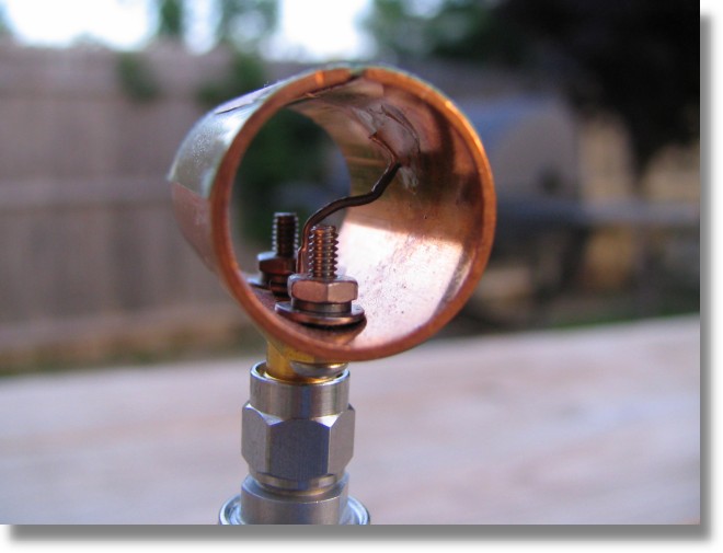
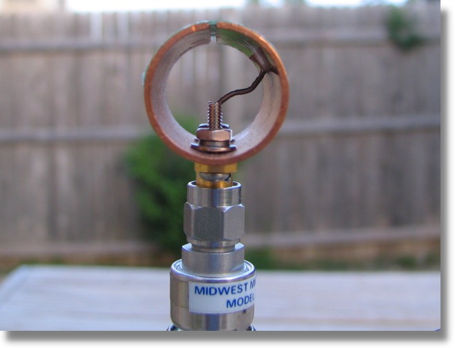
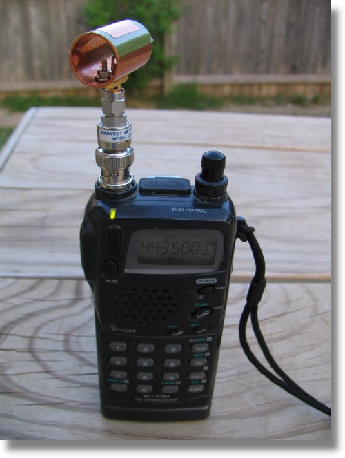
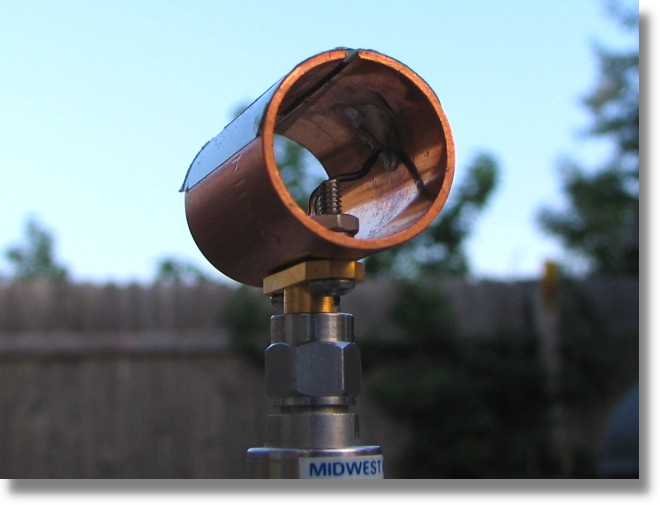
(click to enlarge)
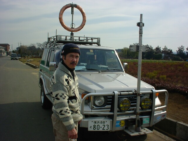
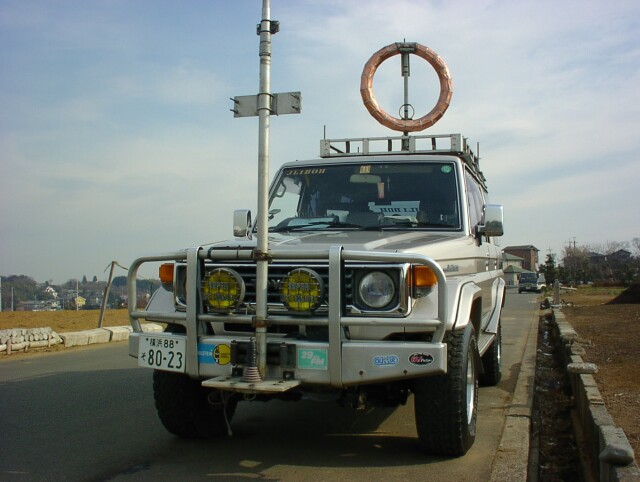
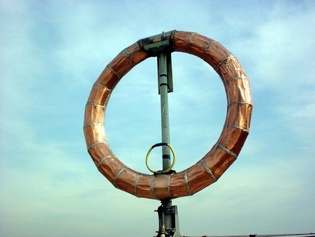
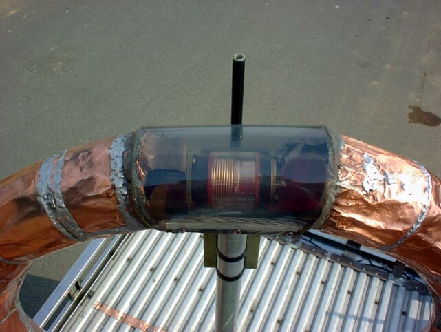
Here are some photos of a very high efficiency loop built by JL1BOH in Japan for mobile use! He really knows what he is doing. I thank him for sending me the good photos.
(click to enlarge)
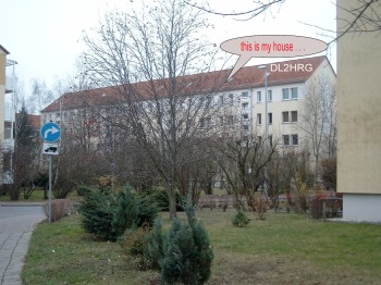
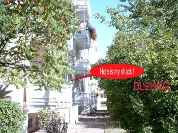
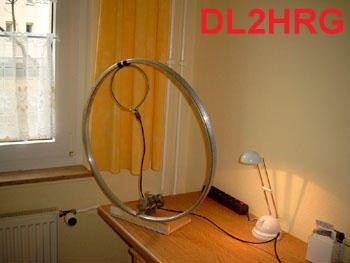
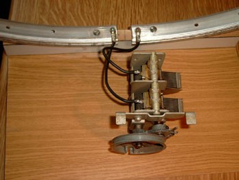
Ruthardt has built a very fine loop antenna using a bicycle rim! He uses it in his bottom floor shack in Germany. He says he has had a lot of success with this antenna and he also says that the antenna is a good compromise antenna for those who have little possibility for a larger antenna. Below are some photos of his home and his antenna. Thanks Ruthardt!
(click to enlarge)
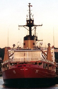
Can you find the small transmitting loop on this U.S. Coast Guard Ship?
Or how about this one?
Here is a nice loop from Poland.
Below in the table is an example of some computed data on a 3 foot diameter loop antenna.
Notice the results when 0.5 ohms of additional resistance is added (last two in the legend). Notice how in this case the loop made from 1" conductor but with additional loss added in has more loss then the quality loop made from AWG 12! This just goes to show that if additional resistive losses are expected in a given design (such as a capacitor with brushes), there may not be much advantage in going to larger conductors - a small conductor will work just as bad! The extra loss resistance will swamp the negative effects of the thinner conductor. Several people have had good results though with just such antennas. Remember that the loss indicated is the loss relative to a perfect antenna and does not take into account ground reflection/pattern gain, loss, etc. Even with a calculated loss the field strength for a particular skywave path may be greater than that of a more efficient antenna of different design. In other words, try it anyway. You may like the results!
[1] Barrick, D. (Jan 1986). "Miniloop Antenna Operation and Equivalent Circuit". Antennas and Propagation, IEEE Transactions on. (pp. 111-114). Vol. 34, Issue 1.
[2] Belrose, J.S. (2005). "Electrically Small Transmitting Loops". Antennas and Propagation Society International Symposium, 2005 IEEE. (pp. 29-32). Vol. 1B.
[3] Boswell, A., Tyler, A.J.and White, A. (April 2005). "Performance of a Small Loop Antenna in the 3-10 MHz band". Antennas and Propagation Magazine. In IEEE. (pp. 51-56). Vol. 47, Issue 2
[4] Burberry, R.A. (23 Oct 1990). "Electrically Small Antennas: A Review". Electrically Small Antennas, IEE Colloquium on. (pp. 1/1- 1/5).
[5] Kraus, John D. (1984). "The Small Loop Antenna". In McGraw-Hill (3rd ed.). Electromagnetics. (pp. 665-666).
[6] Kraus, John D. and Marhefka, Ronald J. (2002). "The Loop Antenna". In McGraw-Hill (3rd ed.). Antennas For All Applications (pp. 197-221). chap. 7.
[7] The American Radio Relay League (1988). "Small High Efficiency Loop Antennas for Transmitting". The ARRL Antenna Handbook. In (15th ed.). (pp. 5-14). Table 4.
[8] K. Siwiak, KE4PT and R. Quick, W4RQ, “Small Gap-resonated HF Loop Antenna”, QST, Sep. 2018, (pp. 30–33).