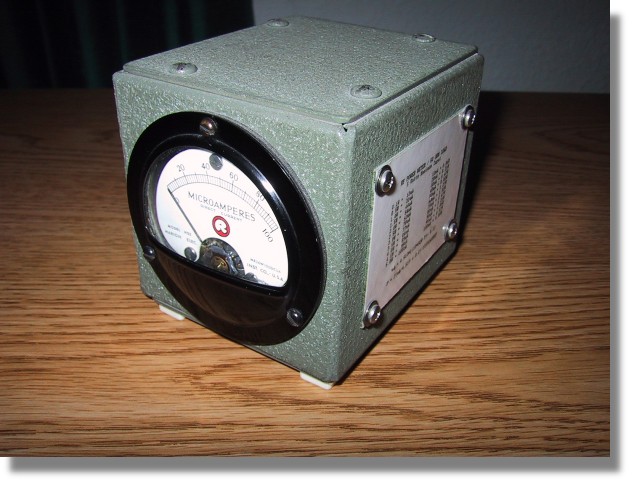

Many years ago I acquired a antique field strength meter and probe kit that did not function. However, the meter had a fast response time and a good enclosure and I thought it would make a good piece of test equipment. I designed the following circuit around what I had and it has worked out well for me.
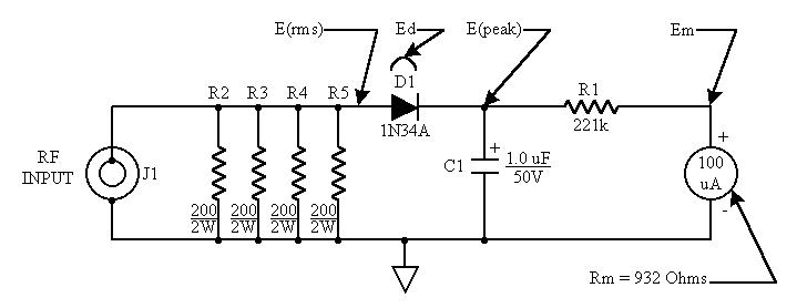
The schematic below is of my QRP power meter and dummy (50 Ohm) load combination. The 50 Ohm load consist of resistors R2 through R5. The four 200 Ohm resistors in parallel combine to make 50 Ohms. I used four resistors because this minimizes the component lead inductance of the resistors as well as distributing the power dissipation. The meter is simply a current meter with a known internal resistance configured as an RF voltmeter. D1 rectifies the RF voltage across the load resistors and C1 charges to the peak of this rectified voltage. The capacitance of C1 is chosen so that the time constant of the RC circuit consisting of C1, R1 and the meter's resistance is long compared to the RF cycle. R1 is chosen so that when the RF power applied is 5 Watts the meter reads full scale.
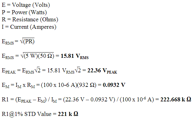
The calculations are as follows:
The internal resistance (Rm) can be found by constructing the simple circuit below and performing the following calculations:
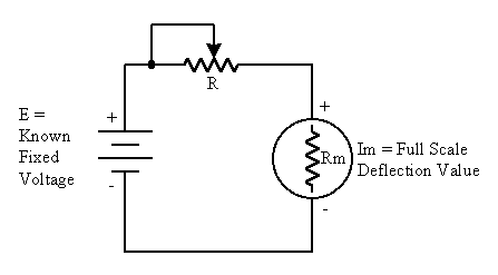
Adjust R until the meter reads it's full scale value. Be sure to start with R at it's maximum value to prevent damage to the meter. Solve the following equation to find the meter's internal resistance.

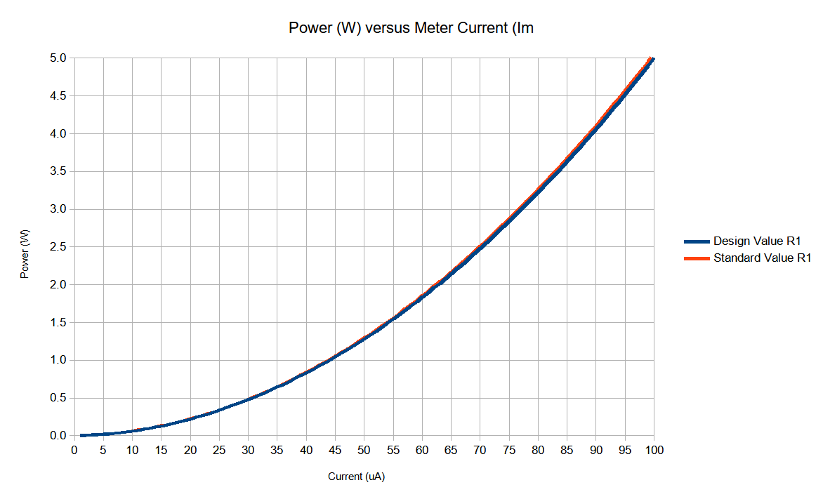
Please note that at power levels below about 100 mW there is a possible error caused by the diode's nonlinear response in this region and has been ignored in this design. Below are two versions of the same spread sheet to perform calculations base on your own meter's internal resistance and maximum scale. It also compares the results of using the calculated values of R1 versus the standard available component values of R1.
QRP Power Meter.xlsx - QRP Power Meter Worksheet in Microsoft Excel
QRP Power Meter.ods - QRP Power Meter Worksheet in open source format (ex., LibreOffice Calc)
