A few years ago I built a little Rock-Mite transceiver for 40m. Since I enjoy using End Fed Half Wave antennas so much I built a small coupler to use with my Rock-Mite. The coupler converts the high impedance end of the End Fed Half Wave antenna down to 50 ohms. Since my unit was to be used in the field I wanted the option to forego using coax cable altogether. In the end, I ended up with a convenient little coupler that easily transforms the high impedance down to 50 and works from 40m all the way to 17m with only a single adjustment. It mounts directly to the rear of the transceiver.
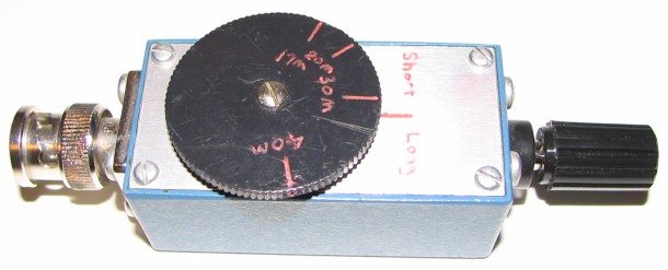
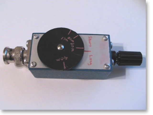
As you can see by the above photo I used an old Pomona enclosure that I had laying around. The Pomona box originally had a jack BNC connector on one end and a plug BNC on the other. For this application I removed the jack and installed a banana plug jack. The coupler mounts directly to the rear of the rig via the BNC plug and the End Fed Half Wave antenna connects directly to the banana jack.
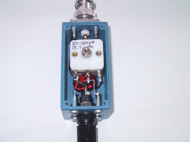
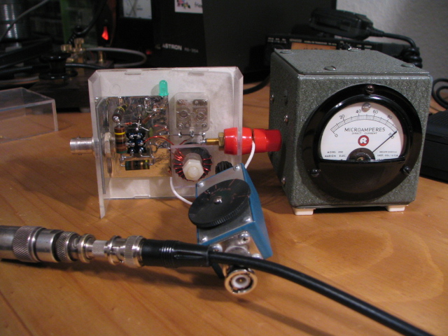
The circuit uses a 20 to 160 pF "polyvaricons" variable capacitor and a T-50-2 core wound with 28 turns of AWG 24 enameled wire for the secondary winding with one 3 turns of AWG 24 for the primary winding and shown in this photo. This works out to an impedance transformation of 50 ohms to 4356 ohms. I was trying for a 10:1 turns ratio but I optimized the secondary's number of turns so that the parallel tuned circuit would resonate in a more centered part of the capacitor's tuning range. It is hard to get 2.8 turns on the primary ;-)
Using the my favorite adjustment method I marked on the dial with a resistive match should occur at every band. When connected to an antenna, if the lowest SWR (peak noise on receive) doesn't occur at the predetermined point on the dial then the antenna is either too short or too long. A low SWR can still be achieved but common mode current (RF on the rig, operator, etc.) will be probable and everything you touch will cause the SWR to change. When things are properly adjusted this will not occur. If you are nervous about it go ahead and attach your favorite "counterpoise" to this coupler but my experience is that if the coupler and antenna are adjusted properly a discrete "counterpoise" isn't required due to the return side of this coupler being connected to the rig and accessories. Little current flows through the "counterpoise" when the antenna is resonant unless the "counterpoise" approaches 1/2 wave length itself.
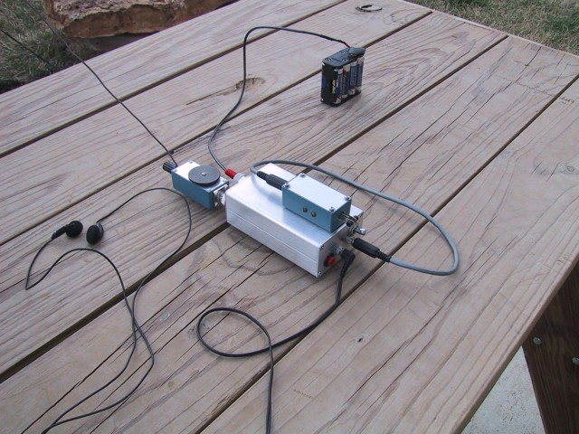
In regards to loss, I connected two similar couplers end-to-end at 20m and measured a loss of 0.97dB. This equates to less then 0.5dB per coupler. Here is how I did it:
First, I connected the high impedance ends of the coupler on this page to those on my 20m coupler. I measured the transmitter power at 5W on 14.050 MHz without the couplers as shown here using my power meter and dummy load combo. Next, I inserted the two couplers into the line has shown here and measured the power again. This time I measured 4W. This calculates to a total of 0.97dB. Granted, my instruments are not lab grade or metrology calibrated devices but I am confident in the data based on comparisons that I have made in the past to such high grade instruments.