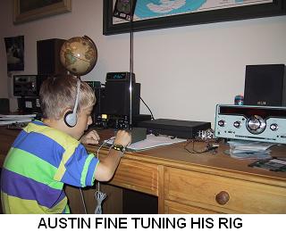
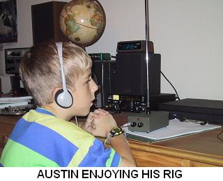
Back in 2002 my then 7 year old son Austin, now KE5PBW, wanted me to help him build a radio. At that time I helped him build a cigar box crystal radio set. He enjoyed that radio but since then he has taken a liking to CW and his simple cigar box set would only receive AM. He wanted a receiver that he could help build yet would receive CW and voice (AM/SSB) and on top of that it had to have a built-in antenna so that he could take it places and/or keep it by his bedside. Now it was hard to convince him that those were some pretty serious constraints but after some thought I realized that a regenerative receiver was probably the answer. The circuit could be simple yet sensitive enough to use a small whip antenna and could demodulate CW, SSB, and AM with the proper setting of the regeneration (feedback). I chose to make the receiver for 40m since on that band there is usually something to hear on CW/SSB 24 hours a day and at night some shortwave AM broadcast can be heard as well.
So in the summer of 2003 we set out to construct Austin's receiver. He was 8 years old at the time. I did the stuff that required drilling and painting, such as most of the hardware related stuff, but I showed him where and how to solder the parts. The enclosure was purchased from Fry's Electronics and I painted it olive drab to make it look like a cool piece of military gear. All of the other components were found in my "junk box". I tinned and cut a piece of unetched double sided circuit board and mounted it into the enclosure. This made a place to mount the parts using "ugly construction" (part to part, point to point). A little bit of hot glue made the larger capacitors pretty good standoffs for other components. The hardest part of the construction was mounting the polyvaricon tuning capacitors to the front panel. This required some precision drilling and countersinking of the screw holes. I showed Austin where to mount the components but I let him do most of the soldering. Below is the result of his hard work.
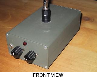
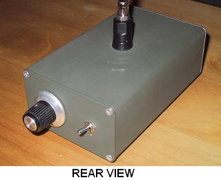
The above circuit of this receiver is very simple. The telescoping whip antenna is capacitively coupled via C2 to the high impedance end of the tuned circuit consisting of L1, C3, C4, C5, C6, and the polyvaricon VC2. This allows for maximum sensitivity with such a small antenna. The received signals at the tuned circuit's resonant frequency are coupled to the active FET device Q1 through an old fashioned "grid leak" capacitor (C7, R2) circuit. Positive feedback is afforded by the "Tickler Coil" L2 and the "Throttle Capacitor" VC1. VC1 controls the amount of feedback so that optimum regenerative can be obtained. RFC1 and C1 provide RF decoupling for the DC supply. LED1 provides a positive indication that the receiver is on so that it will be less likely to be left powered on killing the battery. R3 provides the proper DC source bias for Q1 while C8 provides RF bypassing allowing only the baseband audio to be supplied to AF coupling capacitor C9. VR1 controls the volume of the receiver while U1 and its associated components create a conventional LM386 audio amplifier circuit. The headphone jack J2 is wired so the ordinary stereo headphones can be used.
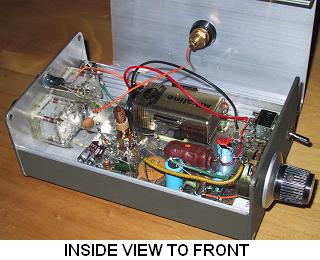
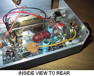
The photos below show the inside of the receiver. The main tuning capacitor and the throttle capacitor can be seen to the left (front) side of the chassis. The volume control and on/off switch can be seen to the right (rear). The 9V battery is mounted in a clip that is attached to the main circuit board via double-sided foam tape. Also to the left you may notice several polystyrene capacitors. These comprise the capacitive side of the tuned circuit. Even though the circuit values were calculated, in reality we had to add and subtract polystyrene capacitors to get the receiver to work exactly on 40m. We also wound L1 and L2 on a vertical coil from and inserted a small tuning slug to facilitate fine tuning onto 40m.
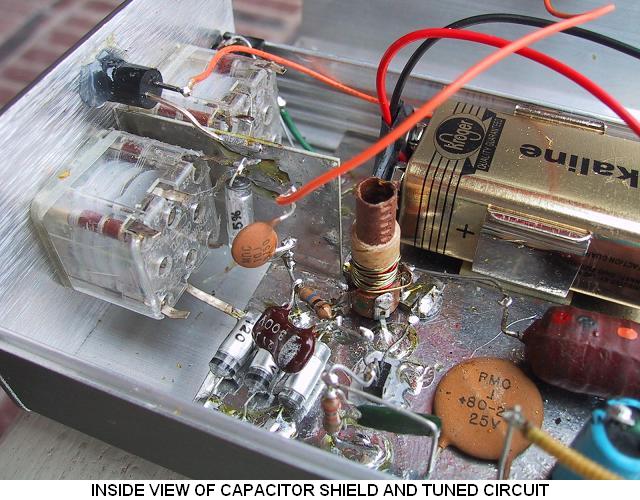
We noticed that there was a lot of interaction between the tuning of the main tuning capacitor VC2 and the throttle capacitor VC1 and was presumably due to the inter-capacitance between the two. We solved the problem by installing a grounded shield between the two as shown below. The shield is soldered to the ground plane of the main board.
We completed the receiver around July of 2003. In the end this simple regenerative receiver meets its design objectives as well as Austin's requirements. The receiver hears lots of good signals on 40m in the CW or SSB modes and the reception of AM signals is adequate with the stronger stations. The frequency stability leaves a bit to be desired however (Note to son: That's what happens when you leave something out of the spec's. ;-). Left alone there is hardly any noticeable frequency drift but since the antenna is closely coupled to the tuned circuit any changes in or near the antenna creates frequency changes. The most troubling frequency shifts are created by the headphones themselves probably due to the fact that they are effectively part of the antenna's return circuit (along with the operator's head). Efforts to decouple the headphones with toroids met with little success because of the high impedances involved. As long as you don't move around a lot while listening the receiver is fun to play with. If you need a bit of fine tuning just turn your head a bit. The audio quality is excellent and the performance is amazing considering how simple it really is.
With an external antenna and loose link antenna coupling, maybe a single transistor RF buffer stage, this receiver could probably be transformed into a nice little receiver to use along side a simple QRP transmitter.
Of course my son Austin is now looking to build something more sophisticated ;-)